Difference between revisions of "Main Page"
Jump to navigation
Jump to search
m (→COMM) |
m (→COMM) |
||
| Line 36: | Line 36: | ||
GND: BLACK | GND: BLACK | ||
| − | RX: '''RED''' | + | RX: '''RED''' <- '''Be careful!''' |
| − | Tx: WHITE | + | Tx: WHITE <-- Not Connected |
3V3: '''YELLOW''' <- '''Be careful!''' | 3V3: '''YELLOW''' <- '''Be careful!''' | ||
Revision as of 23:10, 29 March 2020
Contents
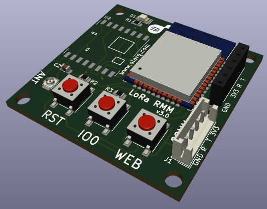
LoRa RMM v3.0

Board
File:RMM 3D v3.0
Caption


caption text text text ...
Connectors
Plastic Box Wall Connectors
SMA
868MHz Antenna plugged at SMA. To avoid malfunctions, it is important to connect antenna before power RMM device up.
4 pin connector
1- 3V3
2- NC (not connected)
3- Rx (MPPT's Tx)
4- GND
PCB Connectors
ANT
uFL connector. SMA / uFL antenna pigtail is connected on ANT.
PRG
J2: Firmware programming connector. Also, it can be used for debugging.
To avoid power supply issues, it is suggested powering device only by COMM connector (J1).
COMM
J1: It is connected to 4 pin external connector.
GND: BLACK
RX:  RED    <- Be careful!
Tx:  WHITE  <-- Not Connected
3V3: YELLOW <- Be careful!
Modes
Firmware Programing
1- Pressing RST button
2- Pressing IO0 button
3- Releasing RST button
4- Releasing IO0 button
Setting LoRa Keys
1- Pressing RST button
2- Pressing WEB button
3- Releasing RST button
4- Releasing WEB button
Normal Mode
<-- MediaWiki has been installed.
Consult the User's Guide for information on using the wiki software.
Getting started
- Configuration settings list
- MediaWiki FAQ
- MediaWiki release mailing list
- Localise MediaWiki for your language
- Learn how to combat spam on your wiki
-->